PALL CORPORATION—LIFE SCIENCES
Case Study—
Designing HMIs for Continuous Antibody Manufacturing
Operator interface design for a modular biologics manufacturing system supporting complex purification workflows in regulated production environments.
At Pall Corporation’s Life Sciences division, I contributed to the design of touchscreen interfaces for biologics purification and filtration systems used in antibody manufacturing.
Working closely with scientists and engineers, I helped translate complex laboratory workflows into operator-friendly machine interfaces used in regulated manufacturing environments.
My contributions included:
Designing touchscreen interfaces for filtration and purification systems used in antibody production
Translating multi-stage laboratory workflows into clear operator control flows
Visualizing system state across the machine train, including pumps, valves, filtration status, and alarms
Supporting operators running complex bioprocesses through clear monitoring and control interfaces
(Roles)
UX Design
(Research Method)
Subject Matter Expert Interviews
Workflow Mapping
Operational Context Analysis
Interface Concept Testing (Informal)
Iterative Prototyping
(Collaboration & Design Tools)
Paper Wireframes
Axure
Miro Board
Context: Downstream Antibody Manufacturing
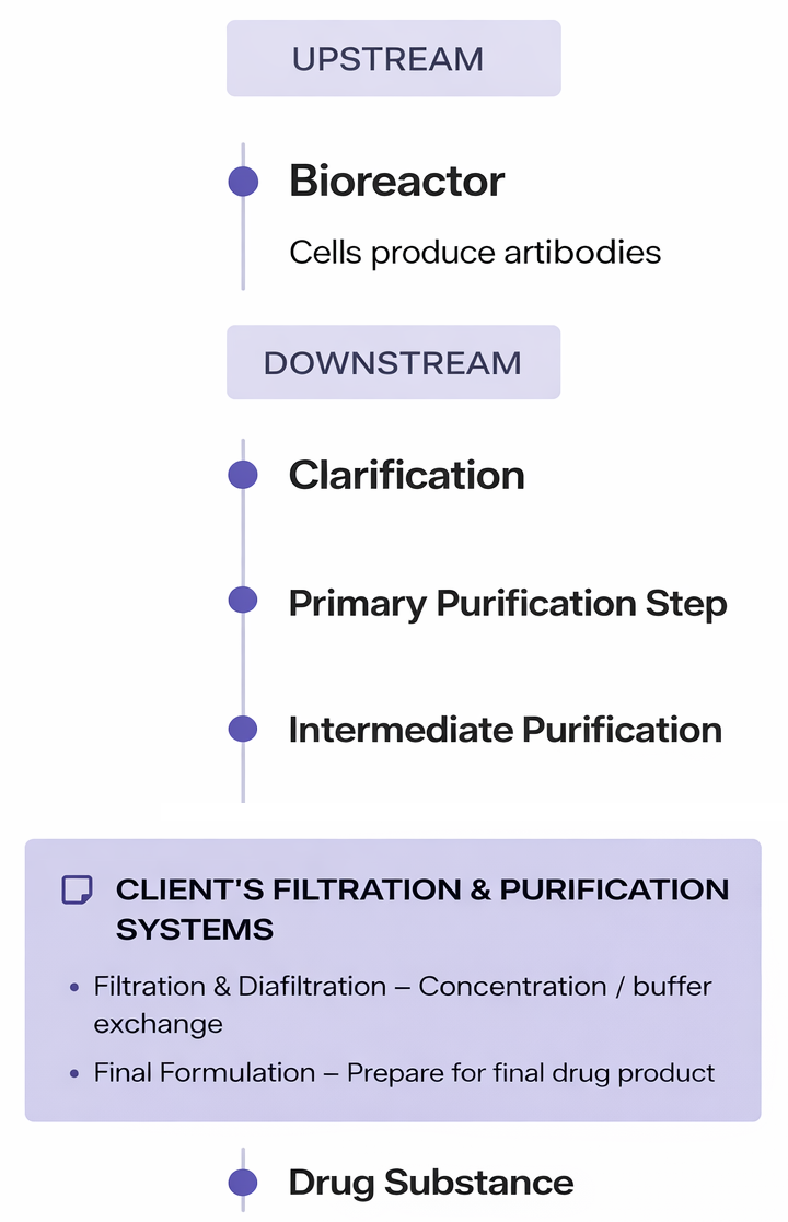
Antibodies used in modern biologic therapies are produced through multi-stage biochemical processes. In manufacturing environments, downstream purification and filtration steps are performed using a train of connected systems, where each stage performs a specialized function within the overall workflow.
Common stages in the process include:
Mixing chemical ingredients
Heating solutions to precise temperatures
Filtering biological compounds
Separating and purifying target molecules
A typical production train may contain five to twenty or more machines, each performing a specialized function within the overall process.
Scientists operate these systems using recipe-driven workflows, where a predefined sequence of steps controls each stage of production. A full production run is referred to as a campaign.
During a campaign, operators must continuously monitor critical process variables to ensure the system remains within safe operating ranges. These include factors such as temperature, pressure, chemical composition, pump activity, and filtration status
Because failures can compromise entire production batches, having clear visibility into the system state is critical.
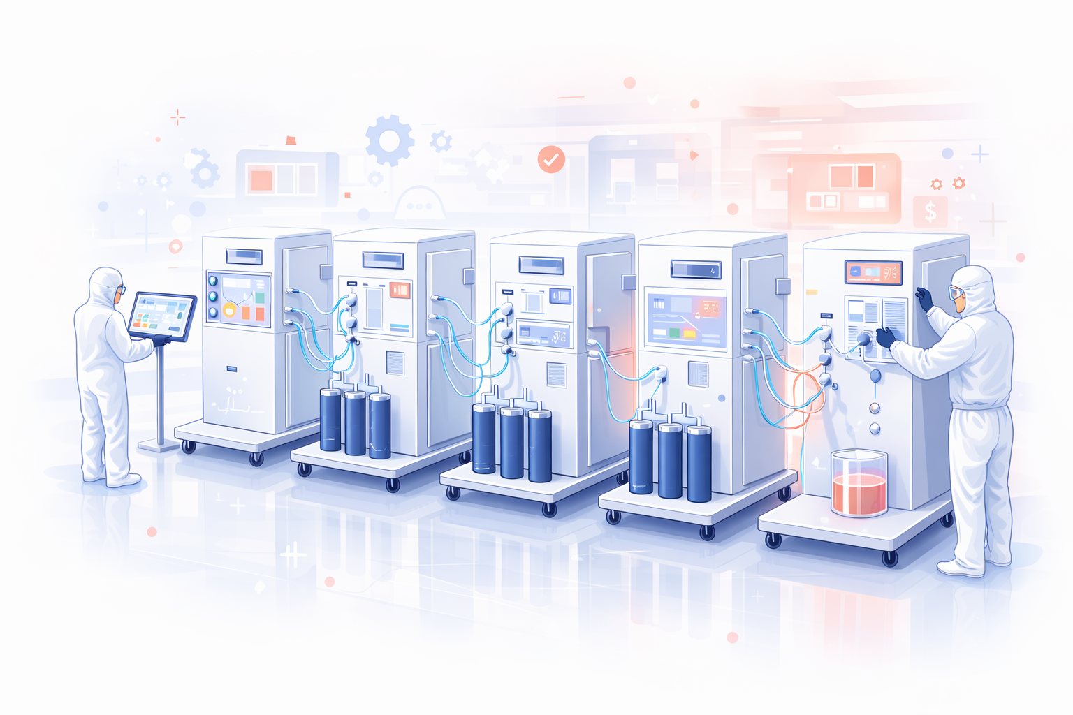
Bioprocess Manufacturing
Biologic therapies such as monoclonal antibodies are produced through multi-stage purification workflows.
Filtration and purification systems operate in the downstream stages of this manufacturing train.
The Problem
Traditional fed-batch manufacturing systems created operational challenges for scientists and operators monitoring biologics production.
Operators manually adjusted process settings such as pump timing, filtration stages, and transitions between steps
Limited visibility into the overall production workflow across multiple machines
Large single-purpose equipment required significant space and configuration effort
System layouts varied between installations, making monitoring inconsistent
Monitoring multiple machines simultaneously increased cognitive load
Failures could compromise an entire production batch
Solution Direction
Pall in 2018-2019 was developing a modular continuous manufacturing platform designed to replace batch workflows with
integrated, scalable systems that improve efficiency, reduce footprint, and provide clearer operational visibility.
From Fed-Batch to Continuous Manufacturing
Fed-Batch System (Legacy)
Large single-purpose machines
Manual transitions between steps
Inconsistent system layouts
High operator cognitive load
Continuous Modular System (Future)
Smaller modular units
Automated continuous workflow
Standardized components
Reduced physical footprint
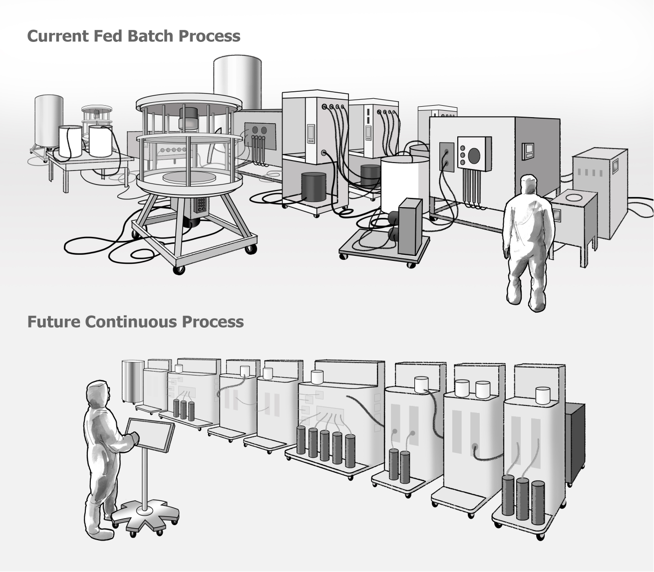
Illustration by the author. Diagram simplified for conceptual clarity and not intended as precise scientific or engineering representation.
The New Continuous Modular System
A modular architecture designed to support continuous biologics manufacturing. Designed to improve efficiency and flexibility in biologics manufacturing, this system represents a significant leap forward from traditional batch processes.
The system architecture was developed by Pall’s engineering teams. My work focused on designing the HMI interface used to operate the system.
CONTINUOUS ARCHITECTURE
Supports continuous purification rather than traditional fed-batch production
Enables steady-state operation across multiple purification stages. This is a major concept in continuous bioprocessing. It means the system runs continuously at stable conditions rather than cycling batch-to-batch.
OPERATIONAL BENEFITS
Reduced physical footprint compared to traditional batch systems
Faster system setup and reconfiguration
Improved scalability from development to production environments
MODULAR SYSTEM DESIGN
Standardized components capable of performing multiple functions
Modules can be configured into different workflows based on production needs
MANUFACTURING ADVANTAGES
Supports single-use system components, reducing cleaning and validation requirements
Enables flexible manufacturing for different biologic products
IMPROVED OPERATOR USABILITY
Modular components are designed for easier installation and maintenance, streamlining laboratory operations and reducing manual intervention.
My Role: UX Designer
Responsibilities:
Conducted interviews with scientists and engineers
Built domain knowledge of antibody manufacturing workflows through SME collaboration
Map operational steps used during manufacturing campaigns
Designed interface concepts for monitoring machine activity
Created interactive prototypes in Axure
Validated workflows with subject matter experts
Key Challenge:
The domain involved complex scientific processes, requiring direct learning from scientists and engineers to understand how the system operated in real-world laboratory environments
Key Insight: Mental Models
Through interviews with scientists, operators, engineers, and subject matter experts, it became clear that operators did not mentally model the system as a technical engineering diagram. Instead, they understood the process as a sequence of steps, similar to following a recipe.
Engineers describe the system using technical flow diagrams (P&IDs) that represent the physical relationships between pumps, valves, filters, and other equipment. These diagrams accurately describe the mechanical structure and fluid pathways of the manufacturing system.
Engineering Representation
Engineering diagrams (such as P&IDs) represent the physical relationships between pumps, valves, filters, and flow paths within the system.
Operational Mental Model
Scientists described the process as a sequence of steps, similar to following a recipe.
This insight informed the design approach, shifting the interface from a purely technical diagram toward a process-oriented view that aligned more closely with how operators think about the workflow.
From Fed-Batch to Continuous Manufacturing
Engineers represented the system through technical flow diagrams that accurately described the physical relationships between pumps, valves, and filtration systems.
Engineering Representation: System Structure
Engineering diagrams (such as P&IDs) represent the physical relationships between pumps, valves, filters, and flow paths within the system.
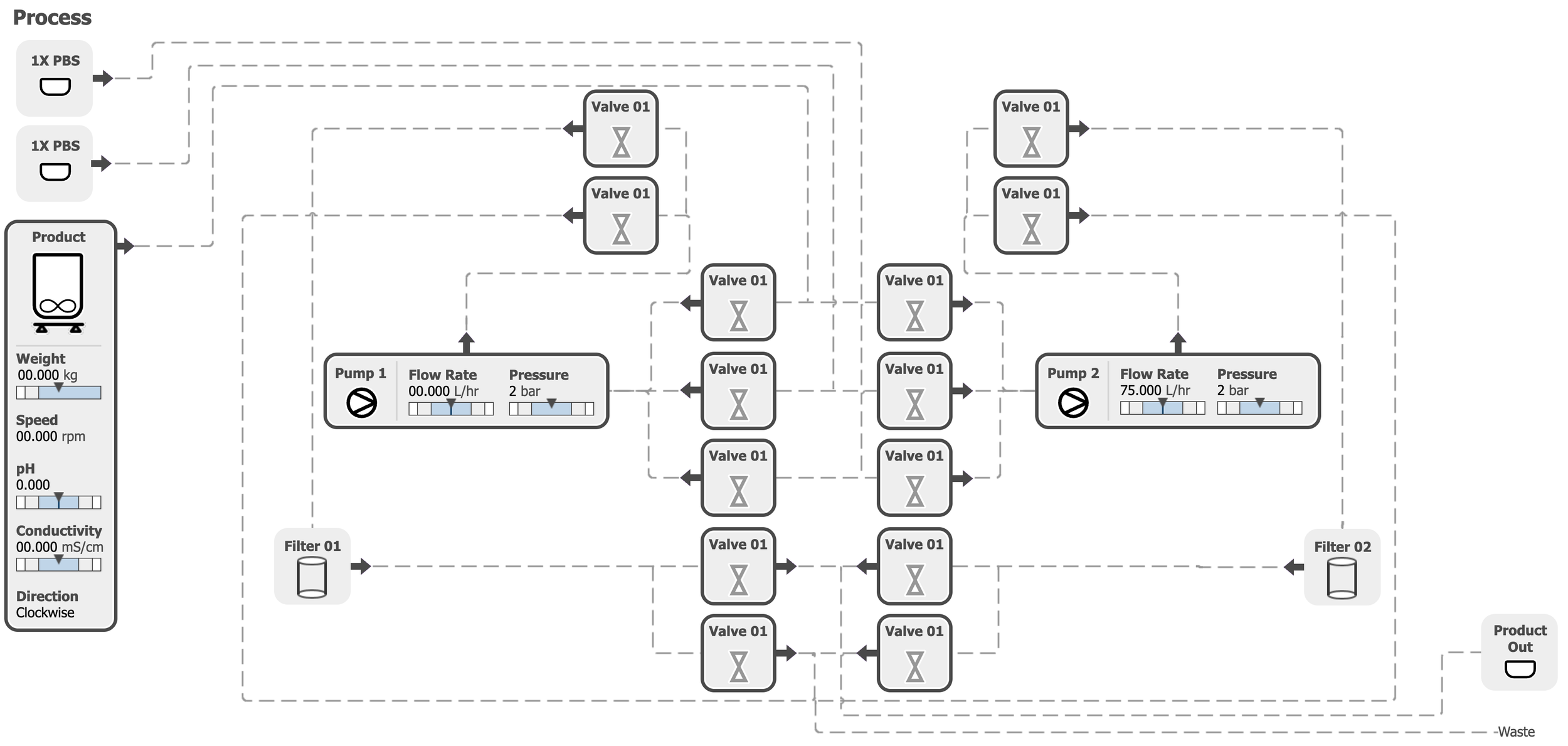
Parameters are shown with default values and do not represent an active system state.
Key Insight: Mental Models
However, scientists and operators described the process differently. They understood the workflow as a sequence of steps, similar to following a recipe, where each stage of the process progressed from one action to the next.
Operational Mental Model: Workflow Progression
Scientists described the process as a sequence of steps, similar to following a recipe.
The Recipe Mental Model:
Each stage of the process follows a clear order, similar to cooking instructions (generic example of steps):
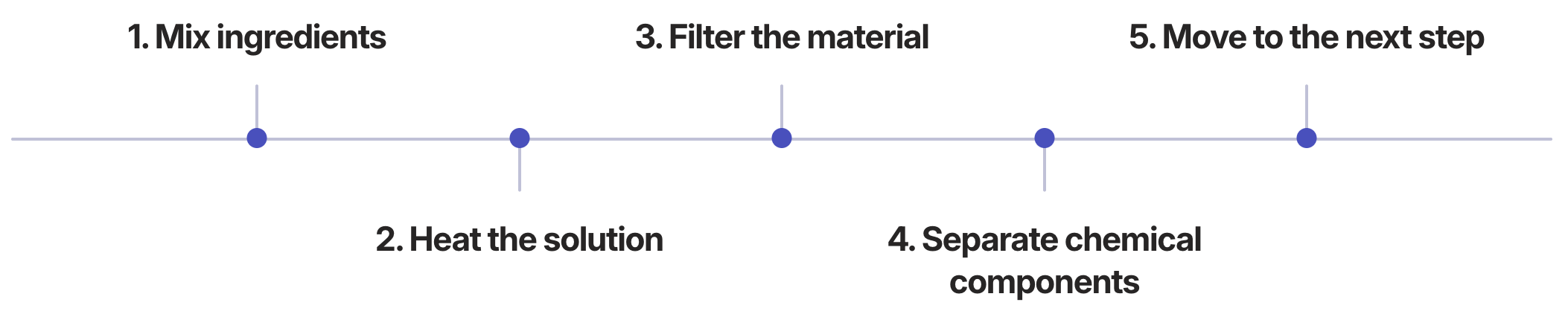
Design Implication: The interface was designed to bridge these mental models by visualizing the process flow in a way that reflects both the physical system architecture and the operator’s step-by-step workflow.
Workflow Mapping
To understand how operators interact with the system during a production campaign, I mapped the key workflows involved in operating the equipment. These scenarios were used in collaborative workshops with scientists and engineers to align the team around how the system would be installed, run, and monitored..
Three Core Scenarios:

Installing and Running a Campaign:
Operators configure the system and start the production process.

Monitoring a Campaign in Steady State:
Operators monitor system variables while the process runs.

Responding to Alarms:
Operators must quickly identify and resolve system alerts when issues occur.
Artifacts
Storyboards illustrating operator interactions across each workflow scenario, used in workshops with engineers and scientists to validate workflows and align the team.
Core Scenario: Installation and Running a Campaign
Illustration by the author. Art simplified for conceptual clarity and not intended as precise scientific or engineering representation.
Step 1 - Operator 1 logs into the HMI to access the batch record.
Step 4 - Operator 1 completes installation of all unit operations; Operator 2 confirms completion.
Step 2 - Operator 1 confirms that all required parts are in the clean room according to the SOP.
Step 5 - Operator 2 starts the batch.
Step 3 - The system detects that the SU manifolds are not installed and guides the operator through on-screen installation instructions.
Step 6 - Operator 2 monitors the startup phase of each unit operation and finalizes any installation steps required for steady-state operation.
Core Scenario: Monitoring in Steady State
Illustration by the author. Art simplified for conceptual clarity and not intended as precise scientific or engineering representation.
Step 1 - The operator views the HMI dashboard, which provides an overview of all unit operations and key parameters.
Step 2 - HMI dashboard displaying system status across all unit operations, with a green “OKˮ banner indicating steady state.
Core Scenario: Monitoring in Steady State
Illustration by the author. Art simplified for conceptual clarity and not intended as precise scientific or engineering representation.
Step 1 - The operator is alerted to an alarm on Unit X via the HMI.
Step 2 - The operator logs in and is directed to the alarm screen, where the triggering deviation is identified.
Step 3 - The operator assesses and diagnoses the issue, then acknowledges the alarm.
Step 4 - The operator brings the supervisor to the HMI and the unit operation if the fix requires manipulation of parameters or components.
Step 5 - The supervisor logs in, resolves the issue according to the on-screen instructions, and resumes the process.
Design Process
I joined the project midstream and helped refine the interface through iterative collaboration with scientists and engineers. We mapped the recipe workflows used in antibody production, interviewed SMEs to clarify operational steps, and explored multiple interface layouts through paper wireframes and whiteboard sessions. Once the workflows were validated with stakeholders, we translated the designs into interactive Axure prototypes.
Designing for Laboratory Environments
The interface design needed to account for the physical realities of laboratory and cleanroom environments where operators monitor biologics manufacturing systems.
Operator Constraints
Operators often interact with the system while wearing:
Protective gloves
Cleanroom suits
Safety goggles and additional protective equipment
These conditions reduce touchscreen precision and limit fine motor control.
Pall systems are also used globally, requiring designs that accommodate operators of different heights and workstation configurations.
Design Solutions
To support these conditions, the interface design prioritized:
Larger interaction targets for gloved hands
Simplified navigation to reduce operational complexity
Clear visual indicators for system status and alarms
Layouts optimized for 13–17 inch touchscreen displays
High-contrast alarm banners visible from across the laboratory floor
Critical Alert Design
Critical alarms triggered full-screen alert states requiring operator acknowledgment before normal operation could continue. These alerts were designed to be visible from a distance so supervisors monitoring multiple systems could quickly identify issues during active production campaigns.
Key Consideration
Because the interface needed to present complex process information on relatively small displays, careful layout decisions were required to balance system visibility, readability, and usability during live manufacturing operations.
Operator Workflow for Antibody Manufacturing Campaign
Prior discovery work, including workshops and process mapping exercises, helped define early concepts for the system. After joining the project, I reviewed these findings and worked with scientists to further understand how recipes were created and executed during antibody production campaigns.
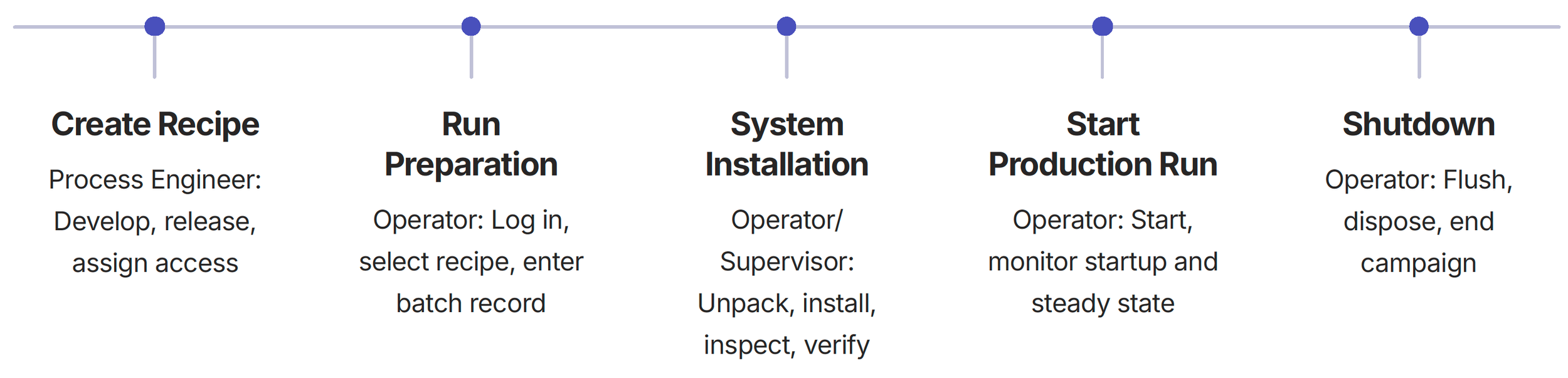
Understanding the operator workflow helped structure the HMI interface around the key phases of a production campaign.
Wireframes
Paper wireframes were used to rapidly explore layouts and interactions following whiteboarding sessions with scientists and engineers. This low-fidelity approach allowed the team to iterate quickly and align on workflows before building interactive prototypes.
Prototypes
Once the wireframes were established, I translated the designs into interactive Axure prototypes.
These prototypes allowed subject matter experts to interact with the proposed workflows and provide feedback before development began.
Translated designs into interactive Axure prototypes
Subject matter experts could interact with proposed workflows
Validated design direction with real users
Interface Prototype Screens
After login, operators are directed to the current machine state, in this case, they're at the beginning at Hardware; where they can configure system inlets, assign mixers, and verify outlets for the process.
Interface Prototype Screens
In Set Up, the operator selects the startup stage of the recipe. During Set Up operation, only the acid and base dose parameters can be adjusted.
Interface Prototype Screens
As Startup progresses, the operator can adjust mixers, pump direction, and inlets within the flow path. Additional parameters such as volume, density, speed, and probe wetting time can also be configured.
Interface Prototype Screens: Live Process Flow
The primary interface screen displays a live process map of the machine train. In this prototype view, parameters are shown with default values and do not represent an active system state.
Key Features
This visualization allowed operators to quickly understand the current state of the production process during a campaign.
Valve States:
Open or close indicators
Pump Activity:
Real-time status
Product Details:
Weight, speed, pH, conductivity, direction
Operational Insight: Alarm Awareness
In large bioprocess manufacturing spaces, supervisors may oversee multiple trains across a wide floor area. Environmental noise and physical distance can make it difficult to quickly identify and respond to critical alarms, leading to process disruption, product loss, and costly downtime.
Delayed response can lead to process disruption, material loss, or costly downtime.
Why? Because minutes can cost millions in these facilities, improving alarm visibility and response time across a large floor space presents a major opportunity for future system design.
Alarm management became a recurring topic during design discussions, highlighting the importance of clear system status visibility in high-value manufacturing environments.
-
Wearable vibration notifications for operators
Mobile alerts identifying the affected unit
Location-aware alerts that direct operators to the affected train
-
Color-coded beacon lights on equipment
Facility-wide visual alarm indicators
Severity-based alarm signals
Zone-based lighting indicators
-
Floor or spatial lighting directing operators
Digital facility map on HMI
Digital facility map highlighting alarm location
Directional indicators on nearby HMIs
-
Lights mounted above each train
Alarm causes local light flashing visible across the room
-
Helmet LED indicator or vibration
HUD-style indicator in safety glasses (future concept)
-
Instead of a general alarm, a directional beacon sound from the machine itself
-
Large wall-mounted display showing a real-time facility map with alarm locations
A digital twin floor map shows the real-time status of equipment across the manufacturing floor.
-
If alarm not acknowledged:
Escalate to supervisor
Escalate to maintenance
Escalate to central control
Escalation logic increases alarm visibility by alerting additional personnel if an issue is not addressed.
Outcome & Impact
The Axure prototypes established the interaction model for the modular manufacturing system HMI. The design mapped closely to the final interface and served as the foundation for engineering implementation.
Contribution
The work contributed to the design of a clearer and more intuitive system interface for monitoring downstream antibody manufacturing processes. By improving system visibility and reducing cognitive load for operators, the design supported safer and more efficient production workflows.
Collaborative Validation
Conducted design workshops with scientists and engineering teams
Facilitated usability validation sessions with subject matter experts (SMEs)
Iteratively refined the interface based on operational feedback and workflow reviews
Operator Improvements
The redesigned interface enabled operators to:
Quickly understand overall system status during active campaigns
Monitor multiple machines and process stages in real time
Identify and respond to alarms more quickly